
This will cover my installation of new horns, relay and fuse without front bumper removal. There are already several threads that cover this. After reading through them, I still found the wiring of the relay unclear. Here, I'll spell out what worked for me.
I chose to remove the grille only, leaving the bumper facade in place. Although bumper removal would have created more room to work, I had no problems.
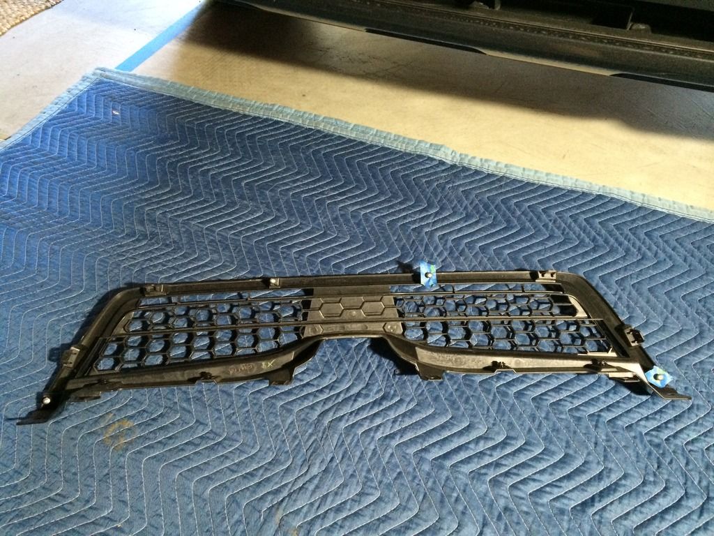
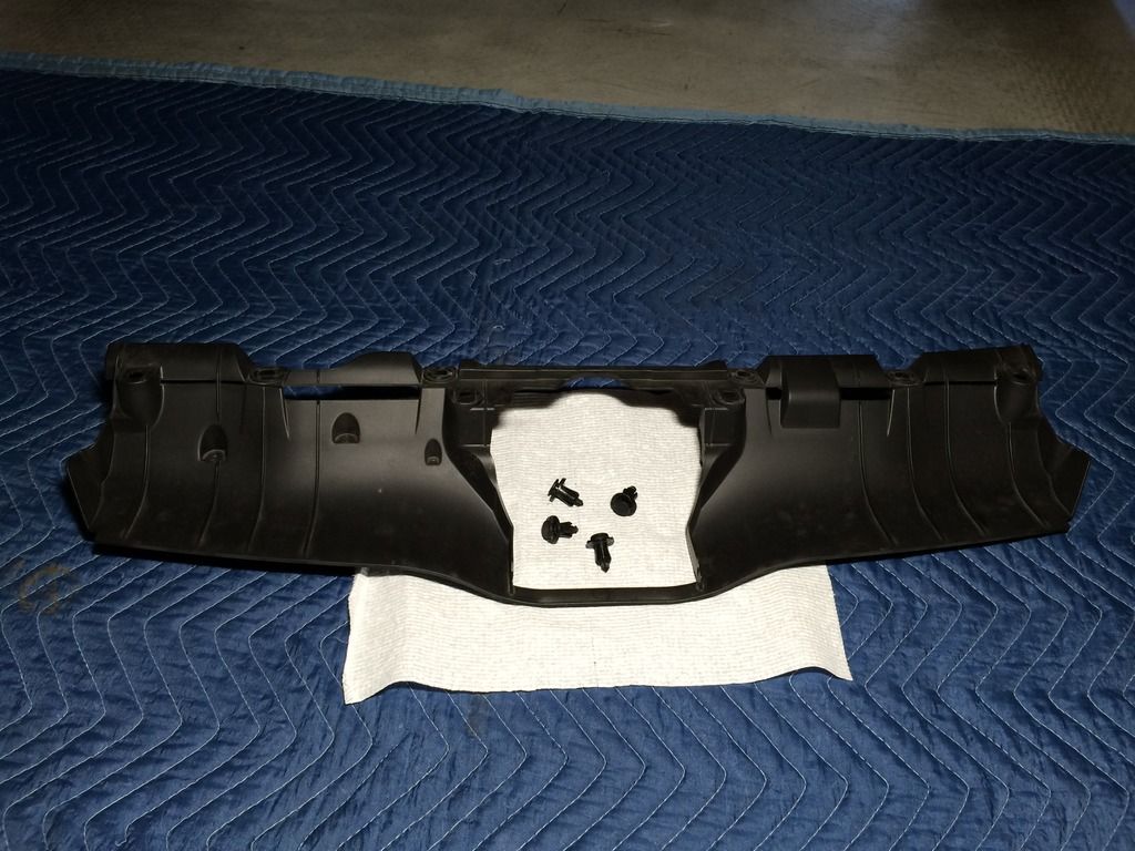
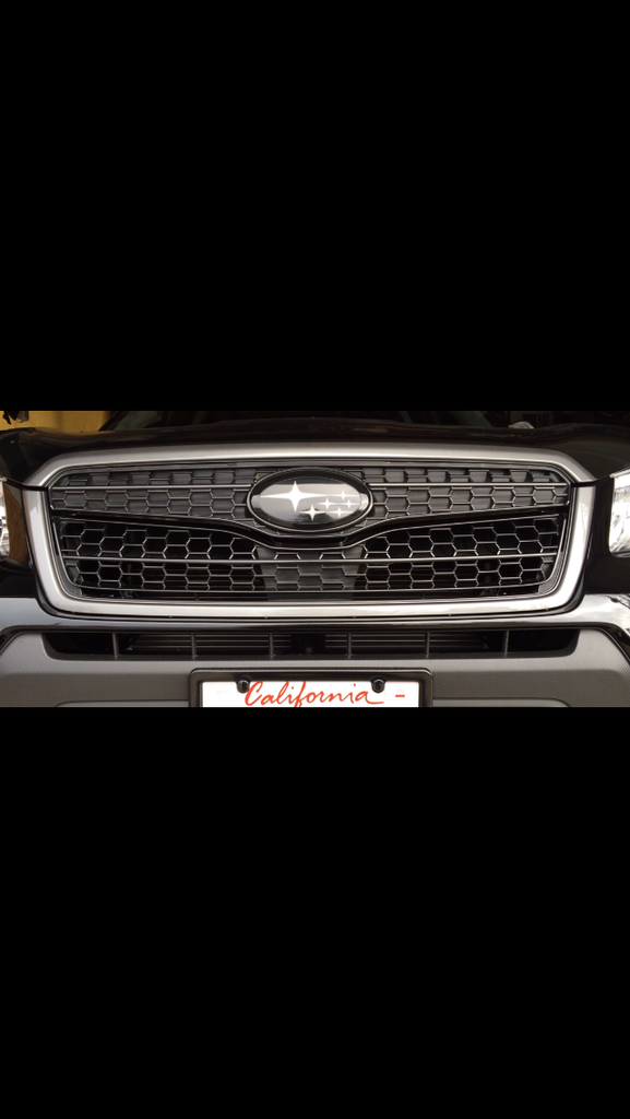
Six plastic fasteners and four screws hold it on. In the photo I put the silver screws back on to show their locations. Blue tape highlights two of them.
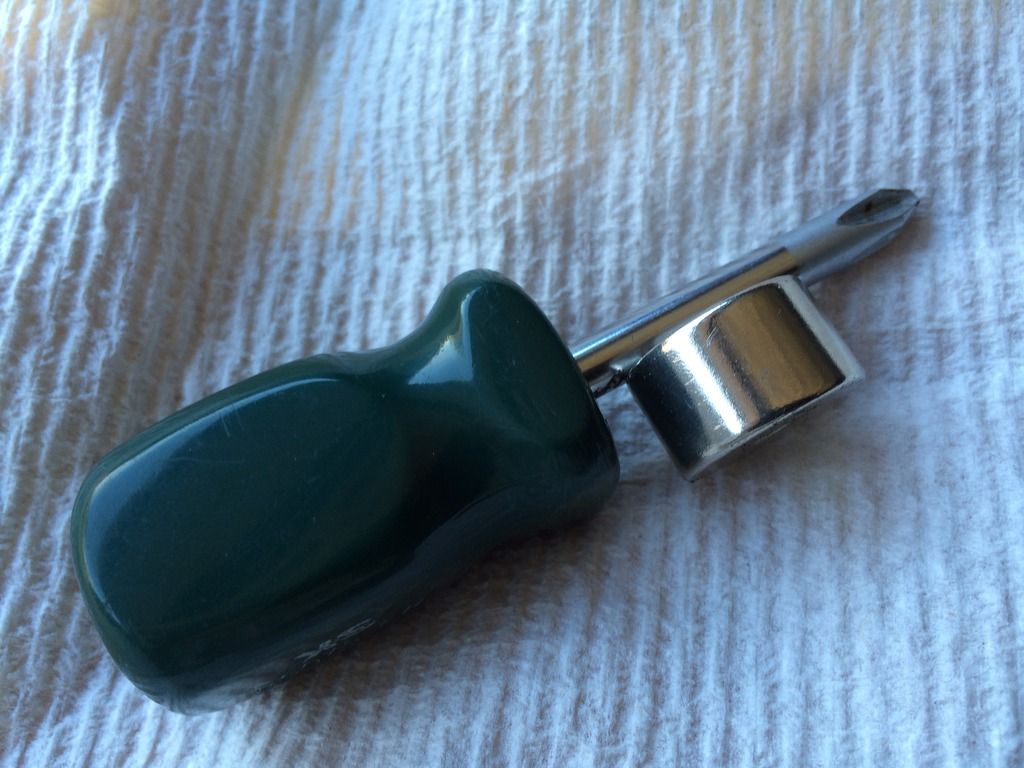
The two screws at the bottom were a little tricky to reach. To keep them from falling, I stuck a strong magnet to the screwdriver.

I removed these two plastic things too.

Here's one of the stock horns.
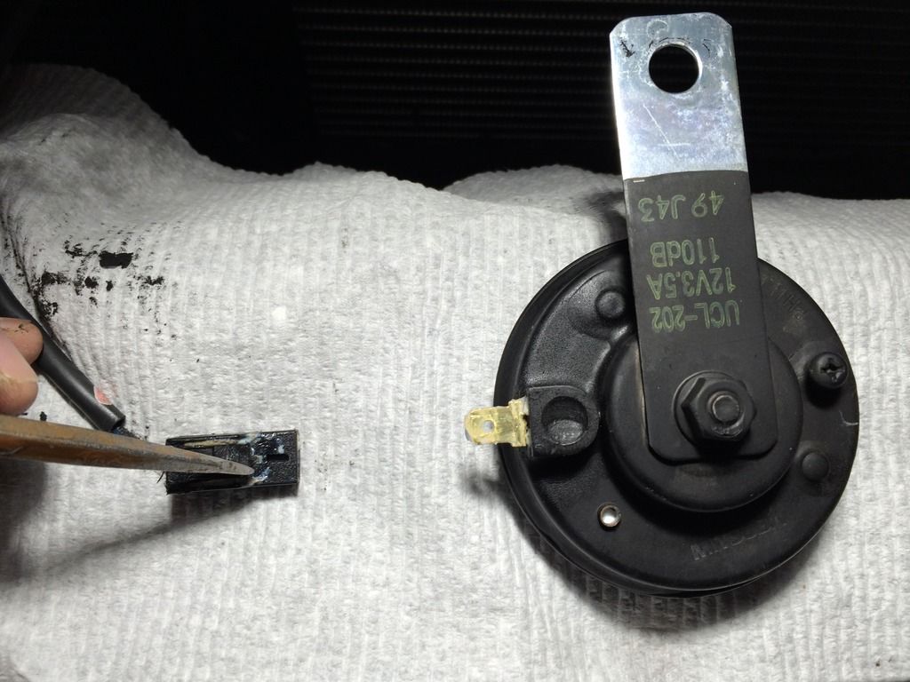
It has a slide-on connector, but you'll need to press the "button" as shown by the tip of the screwdriver. While pressing the button, pull the wire off. You can do it with your fingers, I used the screwdriver in the photo for visual clarity.

There's a second horn. The arrows point to it, X marks the horn.

A 10mm bolt is used here. This is the most cramped area of the job. With this install method you can leave this one in place if you want. I left a horn wired here but I switched it for the other stock horn which had a lower tone that I preferred. In the unlikely event that the aftermarket relay fails, this horn will still sound.
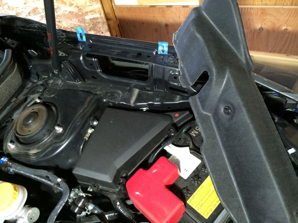
I spent some time deciding where to put the relay and fuse. I settled on the protected area shown near the battery. Two plastic fasteners come off then the shroud can be removed--be careful, it's some sort of fiber material which bends easily. The blue tape/arrows point to two bolts that will become the mount points for the relay.
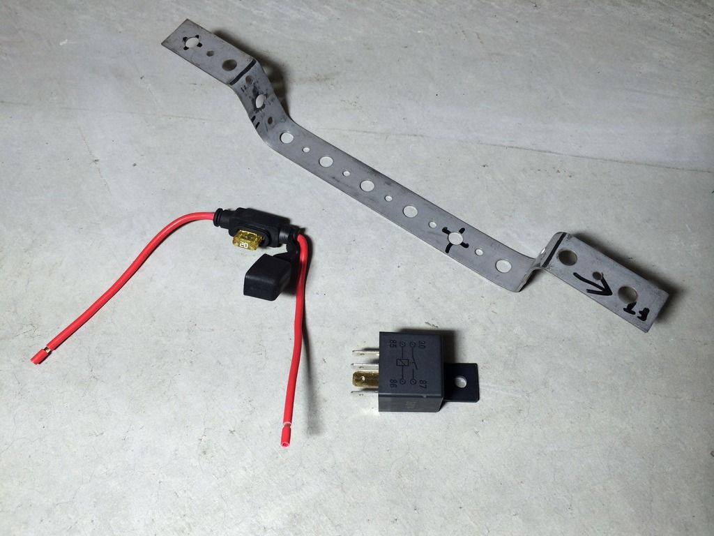
To hold the relay and power fuse, I used a piece of metal strap which I bent as shown. (Hardware store, electrical/plumbing aisles)
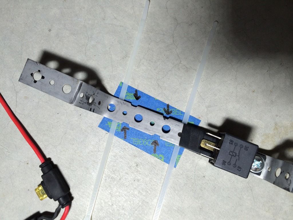
Electrical tape wrapped below relay to avoid a short. The four arrows point to notches that I cut to keep zip ties in place.
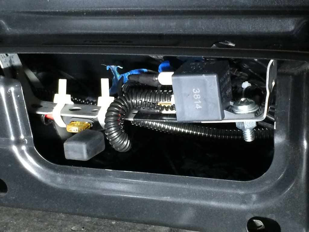
The bracket is held in place two mount-point bolts (a couple photos back). I also had to loosen a screw in front of the bolts. The bracket slips between the metal where those two bolts go. The relay is mounted with the prongs facing the rear of the car. The fuse is zip tied under the bracket. (Instructons said to mount the relay with the prongs down but I chose this instead)
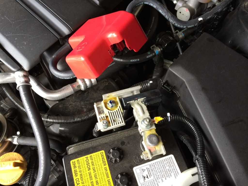
Power comes from the positive battery post using a ring connector. It goes through the fuse to the relay. Because I connected the power directly to the battery, I had to trim the red plastic shroud that covers the positive post as shown.
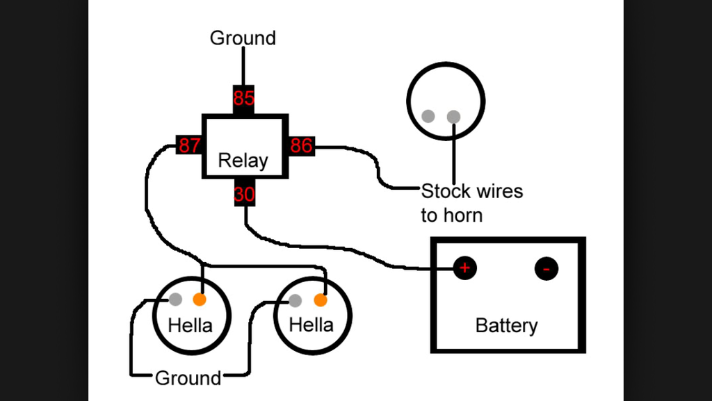
Heres a clear wiring diagram that I got from Google images. Be sure to check the wiring diagram that comes with your kit. The following applies to my relay and setup. Verify before you assume it applies to yours.
Because the bracket that I made is well grounded, I ran #85 to the bracket with a short wire. #30 went to one end of the fuse, the other side of the fuse went to the positive battery post. Each horn has two spades. Both horns ground to their mount points with a short wire from from one their spades. The other spade on each horn gets wired to #87 .
I connected the wire from the center stock horn to #86 . Relay post #86 was the part that was unclear to me. I kept trying to figure out how to splice directly into the wires from the horn button. I finally figured out that I just needed to use the stock horn wire from the horn itself. When that wire is activated by the horn button, it activates the aftermarket relay and horns.

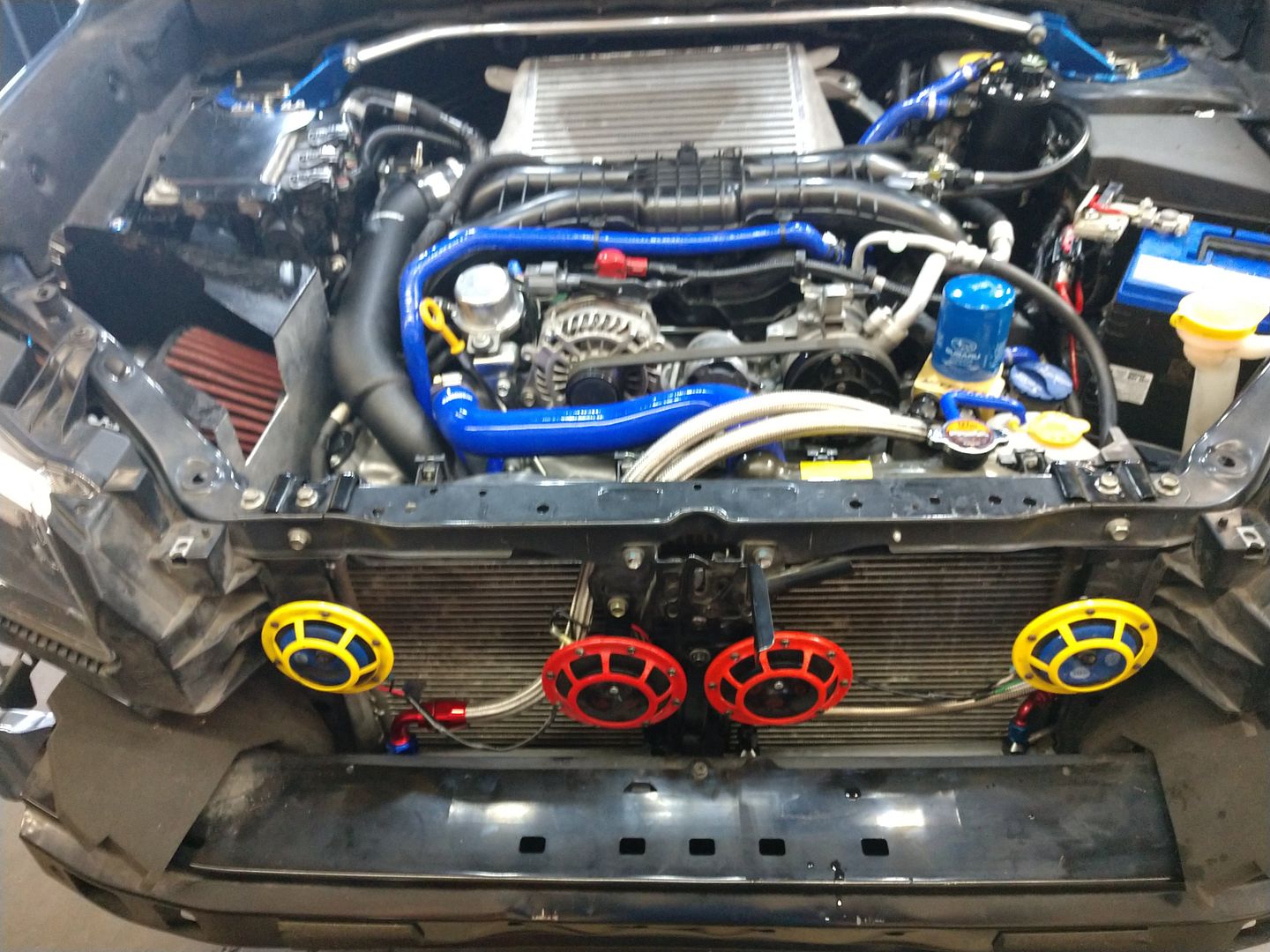
I mounted the horns to some existing holes as far to the sides as possible. I had to trim some metal and plastic because I wanted the brackets to hang straight down.
I used dielectric grease and shrink tubing at all connections, wrapped the wires in conduit loom and zip tied the loom out of sight. I'm not detailing the actual mounting of the horns because there are so many ways to do it. (Just Google images for lots of ideas)
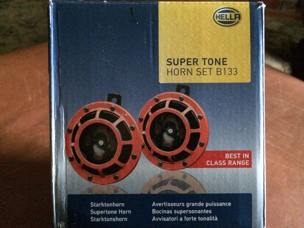
I repainted the red horn grilles black so that they're nearly invisible.
I didn't make a before/after audio recording, those can be found elsewhere.
This project took me the better part of a day to complete, largely due to struggling with how to wire relay #86, deciding where to put the relay then making the bracket. It turned out clean and solid and I'm happy with the results.
If you're considering a horn upgrade, I hope this helps your decision.

I chose to remove the grille only, leaving the bumper facade in place. Although bumper removal would have created more room to work, I had no problems.

Six plastic fasteners and four screws hold it on. In the photo I put the silver screws back on to show their locations. Blue tape highlights two of them.

The two screws at the bottom were a little tricky to reach. To keep them from falling, I stuck a strong magnet to the screwdriver.


I removed these two plastic things too.

Here's one of the stock horns.

It has a slide-on connector, but you'll need to press the "button" as shown by the tip of the screwdriver. While pressing the button, pull the wire off. You can do it with your fingers, I used the screwdriver in the photo for visual clarity.

There's a second horn. The arrows point to it, X marks the horn.

A 10mm bolt is used here. This is the most cramped area of the job. With this install method you can leave this one in place if you want. I left a horn wired here but I switched it for the other stock horn which had a lower tone that I preferred. In the unlikely event that the aftermarket relay fails, this horn will still sound.

I spent some time deciding where to put the relay and fuse. I settled on the protected area shown near the battery. Two plastic fasteners come off then the shroud can be removed--be careful, it's some sort of fiber material which bends easily. The blue tape/arrows point to two bolts that will become the mount points for the relay.

To hold the relay and power fuse, I used a piece of metal strap which I bent as shown. (Hardware store, electrical/plumbing aisles)

Electrical tape wrapped below relay to avoid a short. The four arrows point to notches that I cut to keep zip ties in place.

The bracket is held in place two mount-point bolts (a couple photos back). I also had to loosen a screw in front of the bolts. The bracket slips between the metal where those two bolts go. The relay is mounted with the prongs facing the rear of the car. The fuse is zip tied under the bracket. (Instructons said to mount the relay with the prongs down but I chose this instead)

Power comes from the positive battery post using a ring connector. It goes through the fuse to the relay. Because I connected the power directly to the battery, I had to trim the red plastic shroud that covers the positive post as shown.

Heres a clear wiring diagram that I got from Google images. Be sure to check the wiring diagram that comes with your kit. The following applies to my relay and setup. Verify before you assume it applies to yours.
Because the bracket that I made is well grounded, I ran #85 to the bracket with a short wire. #30 went to one end of the fuse, the other side of the fuse went to the positive battery post. Each horn has two spades. Both horns ground to their mount points with a short wire from from one their spades. The other spade on each horn gets wired to #87 .
I connected the wire from the center stock horn to #86 . Relay post #86 was the part that was unclear to me. I kept trying to figure out how to splice directly into the wires from the horn button. I finally figured out that I just needed to use the stock horn wire from the horn itself. When that wire is activated by the horn button, it activates the aftermarket relay and horns.

I mounted the horns to some existing holes as far to the sides as possible. I had to trim some metal and plastic because I wanted the brackets to hang straight down.
I used dielectric grease and shrink tubing at all connections, wrapped the wires in conduit loom and zip tied the loom out of sight. I'm not detailing the actual mounting of the horns because there are so many ways to do it. (Just Google images for lots of ideas)

I repainted the red horn grilles black so that they're nearly invisible.
I didn't make a before/after audio recording, those can be found elsewhere.
This project took me the better part of a day to complete, largely due to struggling with how to wire relay #86, deciding where to put the relay then making the bracket. It turned out clean and solid and I'm happy with the results.
If you're considering a horn upgrade, I hope this helps your decision.